
This post describes the Mitre Sled setup, including installation and trimming of the fence to suit the router bit you intend to use with the jig. We have made a new tool to help setup the jigs before shipping, in addition to another little 3d printed nut holder to help with the fence assembly.
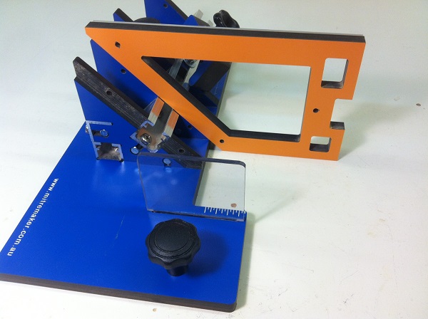
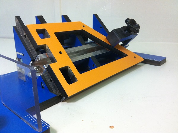
Early versions of the Mitre Sled typically required a bit of fuss with a digital angle measurement device to accurately tune the Mitre Sled angles. We wanted to simplify this process so that this could be done accurately prior to shipping, so we came up with a square with a small protruding aluminum rail as shown below
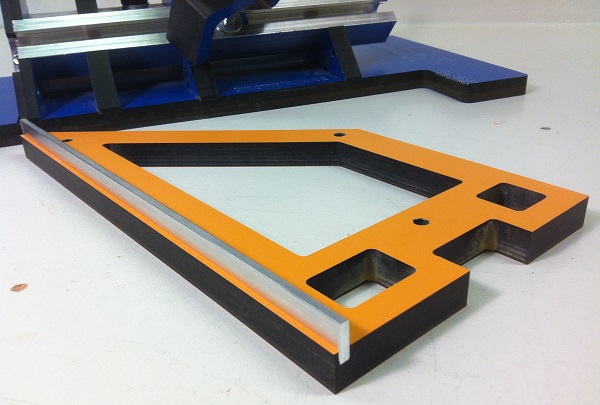
The square has a 135 degree angle for fine tuning the 45 degree upright supports in relation to the table surface and a 90 degree angle for fine tuning the first upright support in relation to the cut face.
With this new square, fine tuning of the Mitre Sled angles are now done in-house prior to shipping.
Next, we wanted to make it more straight forward to attach the fence to the jig. We came up with another little 3d printed nut holder that we are now shipping with the jig and a video to show how to use it to install the Mitre Sled fence.
Once the fence is installed, users need to trim it to suit the router bit that will be used with the jig. This can be a little daunting on a jig you have never used before and you may not cut aluminium on your router table very often either. The video below shows how we do this for two cutters I use most often with this jig.
I hope that with these new little tools and videos, your Mitre Sled setup is even easier so you spend less time fussing and more time making cool stuff.
